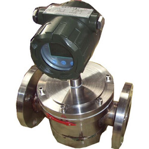
Duplex rotor meter with type UF 1, Introduction Duplex rotor meter with type UF (flow-meter for short) is a new type volumetric flow-meter with special design and precise work. A pair of screw rotors which is the only moving body in the measuring bin splits, measures,delivers and discharges liquid that is measured. A locating gear is added in the structure of this type flow-meter, which makes two rotors have no physical contact when they are moving. When the flow-meter is functioning, it runs smoothly with low noise, less wear and high accuracy. Besides, adaptable viscosity of the flow-meter allows fine particles of the measured liquid pass through in order to make the flow-meter run smoothly. The flow-meter is plated with nickels. As a result, the flow-meter is protected against rot and wears well. And the flow-meter is a substitute for the flow-meter with a material of stainless steel. Characteristics of this flow-meter: 1. Application to thin oil, clean oil, thickened oil, and crude oil with high sediment concentration and high water content and the measured liquid with a wide range of viscosity. 2. The flow of the flow-meter is large. The maximum flow of the flow-meter is twice as large as the normal flow-meter with the same size. 3. The flow-meter with a long service life, high accuracy and high reliability. 4. Less pressure loss. 5. The distance of the wired remote signal is 1,000 meters. Pulse signal output N=0.1L(a pulse is1N); Direct connection with computer networking. 6. Explosion-proof IaCT4(intrinsically safe);Protection class IP65. 2, Principle of operation As is shown in the picture, the flow-meter directly measures the volume of the liquid flow by a pair of revolving special screw rotors. The determination of the liquid flow is finished in the measuring chamber. A pair of screw rotors moves under liquid pressure. A enclosure space is formed between the rotors and the measuring chamber wall (shadow areas shown in the picture ). When the screw rotors revolves once, eight times shadow areas will be discharged. According to this relation, accumulation of the flow will be worked out only if the number of revolutions of the screw rotors are counted. What's more, according to the number of revolutions per second, instantaneous flow can be measured.
3, Technical parameter 1. Nominal diameter and flow range Nominal diameter and flow range shown in the sheet one Sheet one DN mm Flow range(m³/h) Below 0.3mpa.s 0.3~ mpa.s 2~5 mpa.s 5~15 mpa.s 15~50 mpa.s 50~400 mpa.s 400~1000 mpa.s 1000~1500 mpa.s 1500~2000 mpa.s LPG Gasoline Kerosene Light diesel oil A heavy oil B heavy oil C heavy oil High viscosity liquid 8 0.04~0.4 0.04~0.4 0.04~0.4 0.04~0.4 0.03~0.3 0.03~0.3 0.03~0.3 0.03~0.3 15 0.25~2.5 0.25~2.5 0.25~2.5 0.3~3.0 0.3~3.0 0.3~3.0 0.3~3.0 0.25~1.5 25 0.6~6 0.6~6 0.6~6 0.6~6 0.6~6 0.6~6 0.6~6 0.5~5 0.5~4 0.5~3 40 5~20 4.5~20 4~20 3~20 2.5~20 2.5~20 2.5~20 2~13 2~12 2~10 50 6~30 5~30 5~30 4~30 4~30 4~30 3~30 2.5~25 2.5~20 2.5~15 80 30~80 20~80 15~80 12~~80 10~80 8~80 6~80 5~55 5~45 5~39 100 50~180 35~180 25~180 20~250 17~250 10~250 8.5~250 8.5~130 8.5~110 8.5~97 150 70~260 50~260 40~260 30~260 20~340 17~340 15~340 12~190 12~160 12~140 200 100~380 70~380 55~380 45~500 35~500 30~500 25~500 25~280 25~220 25~200 250 200~630 140~630 110~630 90~800 70~800 55~800 45~800 45~460 45~380 45~340 300 300~980 210~980 170~980 140~1100 110~1100 90~110 65~1100 65~720 65~590 65~520 Attention: 1. The flow range of the flow-meter above is of accuracy of 0.5class. 2. If the accuracy of the flow-meter is 0.2class, the upper limit value of the flow range has no change and the lower limit value is counted by 1:5. If the accuracy of the flow-meter is 0.1class, counted by 1:3.
4, Specifications 1. The structure of the rotors
Rotor assembly
2. Double-rotor-transmitter and the whole structure of the smart meter
Chart about double-rotor-transmitter and the whole structure of the smart meter 1. Synchronizing gear 2. Taper bolt 3. Taper bolt 4. Pinion 5. Screws and pads 6. Ring with type O 7. Socket head cap screw 8. Gauge outfit 9. Magnetic coupling 10. Connector 11. Gland 12. Magnetic coupling 13. Button-headed screw 14. Cap 15. Six-angle-screw-and-pad 16. Ring with type O 17. Upper cover plate 18. Adjustable pad 19. Cylindrical pin 20. Rotor 21. Active and passive rotor shaft 22. Stat-or 23. Enclosure 24. Alloy sleeve 25. Bottom Cover Plate 26. Parallel pins with external thread 27. Copper sheathing 28. Alloy column 29. Six-angle-screw-and-pad 30. Adjust screw 31. Socket head cap screw 32. Cylindrical pin 3. Dimension of double-rotor-transmitter shown in the chart below:
Items
model Nominal pressure (Mpa) Physical dimension Flange connection dimension Bolt
4, Representation methods of the type of double-rotor:
Basic types 1 2 3 4 5 6 Illustration Nominal diameter Counter Nominal pressure Feature Sender Working temperature UF Representation: double rotor meter 8 The nominal diameter is 8mm 15 The nominal diameter is 15mm 25 The nominal diameter is 25mm 40 The nominal diameter is 40mm. 50 The nominal diameter is 50mm. 80 The nominal diameter is 80mm. 100 The nominal diameter is 100mm. 150 The nominal diameter is 150mm. 200 The nominal diameter is 200mm. 250 The nominal diameter is 250mm. 300 The nominal diameter is 300mm. W No message header pulse J Mechanical counter E Electron counter H Return-to-zero-mechanical-counter 1.6 The nominal pressure is 1.6Mpa. 2.5 The nominal pressure is 2.5Mpa. 4.0 The nominal pressure is 4.0Mpa. 6.3 The nominal pressure is 6.3Mpa. C304 The rotor is 304 stainless steel. C316 The rotor is 316 stainless steel. CC304 The enclosure and rotor is 304 stainless steel. CC316 The enclosure and rotor is 316 stainless steel. F Sender pulse output I Sender current output A Working temperature-20~+80 B Working temperature-20~+150 C Working temperature-20~+250 D Working temperature-20~+350 ,Connection mode Double rotor meter(UF-caliber N type,UF-caliber A type) 1.Basic type UF-caliber type; "24v+"(red wire)connects DC24v positive terminal; "Negative supply:(white wire)connects DC24v negative terminal; "Impulse"(yellow wire)connects two watch pulse input terminal. 2.Explosion proof type UF-caliber N type, shown in chart 8. 3.UF-caliber A type, shown in chart 9.
Intelligent double rotor meter(UF-caliber C type)
6,Commissioning Double rotor meter with UF-caliber N type The basic types of the double rotor metes have been demarcated and adjusted before delivery. There is no need to commissioning. The transducer connects two time display instrument:first, you should check whether output characteristics (the range, amplitude and pulse width of the Output pulse frequency) of the transducer match input characteristics of the display instrument. You should set up parameters of the display instrument according to the meter factors of the transducer. Besides, check the electric source and wiring system of the transducer and impedance matching. What's more, it is consider that the preliminary amplifier of the transducer is protected against electromagnetic interference. If the flow meter is out of doors, you should take rain-proof measures. Transmission cable is usually twin-core or three-core telecommunication cable with shield and lagging. The net sectional areas are 1.25-2mm2 of multi-strands copper wires. Only one end, especially in the end of the meter, of shielded wire can connect the ground. The electric cable had better a complete one and be packed in the metal tube to avoid damaging machine. If another electric cable is packed in the metal tube, the maximum power of the electric cable is not larger than the minimal power of ten times of the cable of the flow meter. The route of the transmission cable is not parallel with power supply wires and it is not in the concentrated regions of the power supply wires in order to be protected against electromagnetic interference. UF-caliber A type double rotor meter As client's order requirements, the flow output zero and end scale value of the double rotor meter with type A have been adjusted before delivery. After the flow meter functioning, if the flow output zero needs to be adjusted, operating methods as follows:close the valve of the flow meter pipeline and confirm there is no flow in the pipeline. Connect the power supply of the flow meter; Connect ammeter (DC current profile of avometer) to monitor output current of the flow meter. Do some fine tuning on W502 potential device converter circuit board to make output current return to 4 mA. After the flow meter functioning, the scale value of the flow meter can not adjusted. If the adjustment is needed, please deliver the flow meter to the factory. Manufacturer finish it in the standard flow device as your requirements UF-caliber B type Intelligent double rotor flow meter with status display Instrument parameters' settings:(allow engineers to operate) 01.Instrument face plate press key instruction . enter(quit)parameter setting menu:press→and F at the same time in work status. . Cursor shift to right:under parameter setting status press→ . Cursor position value added one:under parameter setting status press↑ . Parametric menu switching:under parameter setting status press F . Cumulative flow cleared:under parameter setting status press F and↑at the same time 02.intrinsic parameters instructions Instrument program has three menus and has three screens to display. There is three point coefficient correction of meter measurement range in each screen. The upper coefficient is flow point frequency value. The lower coefficient is flow meter factor. Three menus can be switched by pressing F. Each menu displaying way and function shown in chart10 Attention:meter's parameters have been set before delivery and no need to adjustments unless special conditions :users need to know the meter parameters of different traffic points of sensor (frequency points) when using three point meter to adjust flow sensor.
10 11 UF-caliber C type double rotor meter with intelligent indicator with status display and 4-20mA output 01.Instrument face plate pressing key instruction Double rotor meter with status display and battery powered 02.Internal parameters Instrument program has four menus and has four screens to display. The first three menus are three point coefficient correction of meter measurement range, which is as same as the double rotor meter with status display and battery powered. The output full value of the fourth menu is 4-20mAl(refers to the flow point of 20mA). Four menus can be switched by pressing F. The displaying way and function from one menu to three menu is as same as revolving flow meter with status display and battery powered. The displaying way and function of the fourth menu is shown in chart11. 7,Unpacking note 7.1 After unpacking the carton, check whether the files and enclosure is in good condition as to packing list. Packing filers:A copy of operating instruction A copy of certificate A copy of packing list 7.2 Observe whether the transportation causes a damage to the flow meter in order to deal with it properly. 8,Ordering instructions 8.1 According to nominal bore, working pressure, working temperature, flow range, fluid types and ambient condition you choose the flow meter of proper specification. When the explosion-proof condition is needed, you should choose explosion-proof sensor and notice anti-hazard classification. 8.2 When matching meter is needed, you should choose the proper specification referring to the corresponding instruction or technicians of my company help you to choose the proper specification as to the information you support. Electric cables of transmission signal should specified the length.
Sold By
PCB Board, Flow Meter, Electromagnetic Flow Meter manufacturer / supplier in China, offering Dual Channel Ultrasonic Water Meter with Built in Battery...


 鲁公网安备37160202000910